| Nixie tubes | |
 Photo:Dieter Waechter |
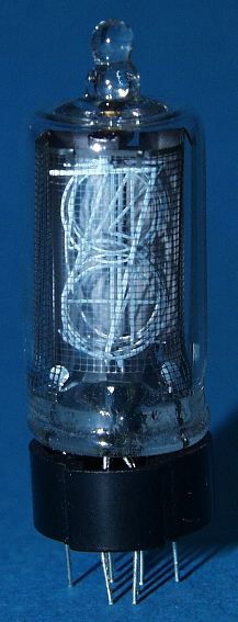
The Nixie Watch uses modern electronics to light up the vintage nixie tubes. The tubes themselves are the B-5870 type, which was designed originally for use in calculators in about 1970. By the time 1973 rolled around, the LED display had taken over the calculator market. Thousands of unsold nixie tubes were left moldering in warehouses, since no one wanted an old-fashioned nixie tube calculator any more.
Fast-forward 35 years. With the proliferation of LCD displays on everything electronic, the quaint 3D display of the nixie tube has a certain appeal. The fully-formed numbers are more aesthetically pleasing than the crude 7 segment displays we have become accustomed to.
The nixie tube works like a neon lamp. It consists of an evacuated glass tube to which a small amount of neon gas has been added. The tube contains ten metal cathodes shaped like numbers 0-9, surrounded by a metal screen anode. When a positive voltage of about 180 Volts is applied to the anode mesh relative to a cathode element, the neon gas surrounding the cathode sees a strong electric field. This electric field causes the electrons surrounding the neon atoms to change energy level, thereby emitting orange photons. The electric field strength with 180V is only high enough to cause the glow to occur very near to the cathode element. The excited condition of the gas that causes it to glow is called plasma. Once the plasma has started, the excited electrons will bump other electrons out of their energy levels, causing the glow to be sustainable at a lower voltage of about 140V. The current that flows through the tube is on the order of one to two milliamperes. A current of less than one milliampere will not light the cathode completely, while more than two milliamperes will wear out the tube prematurely. The cathodes may be switched by less than 140V swing. Since a cathode will not light if the anode-cathode voltage is less than about 120V, it is only necessary to raise the unlit cathodes to a voltage 50V above ground to cause them to stay dark if another cathode is lit in the same tube. This fact is important as it allows the use of some very small cathode driver chips, which reduces the size of the finished watch. The watch is run in multiplexed mode, which means that only one tube is lit up at a time. This can be seen by moving the watch quickly sideways as it displays the time. The tubes display a stroboscopic effect as they turn on and off rapidly. The reason to use a multiplexed display is that it reduces the power requirements. Only one tube is active at a time, and it is possible to use a more-efficient current regulation technique described below. |
| Schematic | |
| Download | The schematic diagram is available as a PDF file by clicking the link to the left. Feel free to print it out and follow along. |
| Display Drivers | |
 |
The nixie tubes are driven by the two chips U3 and U4, which are Toshiba TD62083AFN octal Darlington driver chips. Each driver chip has eight open-collector 50 Volt transistor driver circuits, designed to be driven from logic level signals of about 3V.
Pin 10 of each chip is connected to the cathodes of protection diodes wired to each output pin. The purpose of these diodes is to clamp the output voltage to a safe maximum voltage to prevent damage to the transistors. This clamping voltage is derived by 51V Zener diode D5 from the high voltage tripler’s first stage. Pin 9 of each chip is connected to the emitters of all the driver transistors. It is used to monitor the current drawn by the tube for regulation of the display brightness as described below. |
| Microcontroller | |
 |
The nixie watch employs a PIC16LF722 microcontroller U2 to read the tilt sensor, control the power supply and select which digits to light up. The microcontroller also keeps track of the time of day. The processor runs at a very slow speed to save power. It executes only 8192 instructions per second, so the software that controls the watch as been carefully crafted to operate as efficiently as possible. The power used by the microcontroller is about 10 microamperes. |
| Oscillator | |
 |
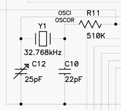
The microcontroller’s oscillator is connected to a standard 32768 Hz quartz watch crystal Y1. This frequency is chosen because it can be divided by two fifteen times to produce exactly one pulse per second. The oscillator circuit has a variable capacitor C12 to allow adjustment of the operating frequency to within a few parts per million (PPM), which corresponds to a few seconds a week timekeeping error. The oscillator is adjusted at the factory to +/-1 PPM at about 25 degrees C.
Any crystal oscillator is subject to both temperature and aging variations. The AT strip crystal used in this and nearly every watch has a negative slope parabolic frequency vs. temperature curve, with the top of the parabola centered at 25C. This means that the watch will run slower if very hot or very cold. |
| Tilt Sensor | |
 |
A triple-axis accelerometer U5 is used to detect when the watch is held at the correct angle for viewing. This device, the ADXL335 made by Analog Devices, contains a micro-machined floating plate held up on tiny silicon springs. The plate is moved by the force of gravity, just as any plate suspended on springs will stretch the springs above it. Sets of interlocking fingers on each side of the plate form capacitors that are used in oscillators. The frequency of oscillation is a function of the capacitance, which is a function of the spacing between the fingers. The spacing is a function of the force being applied to the plate by gravity.
The accelerometer converts the frequency of oscillation of each of the Y- and Z-axis oscillators into voltage, which is read by the microcontroller using an on-chip analog to digital converter (ADC). Thus, the microcontroller is able to learn at what angle the watch is currently held relative to the earth. The scale factor is such that on the scale of 0 to 255 of the ADC, each axis of the accelerometer puts out a value of approximately 128 for 0g, 140 for +1g, and 116 for -1g. The accelerometer is mounted on the rear PC board. It can sense the rotation of the watch as it is brought into reading position from the rest position. The specific quadrant desired is that with the tubes facing up, but with the nipple end above the pin end of the tubes. Since the accelerometer provides indication of polarity as well as magnitude of gravity’s pull, it is able to indicate whether the tubes are nipple-up or nipple-down and face-up or face-down. The relative magnitude of the Y and Z axes indicates the angle within the quadrant, in the sense that Y is the cosine of the angle and Z is the sine of the angle. The accelerometer chip uses about 1/3 milliampere of current, so it would drain the 800 mAH battery in three weeks if allowed to be powered on continuously. Therefore, the chip is only powered up for a few milliseconds at a time, several times a second, to measure the tilt angle. This results in an average current draw of about ten microamperes. |
| Power Supply | |
 |
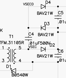
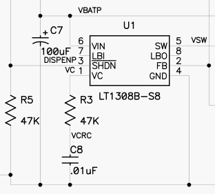
The nixie display tubes require about 180V to light up (strike) the neon gas and about 140V to sustain the orange plasma glow. This high voltage is provided by an LT1308B flyback-mode switching power supply controller chip, U1. The converter uses a 1:12 step-up transformer driven at 600 kHz to make about 60VAC, which is boosted to 180VDC by a voltage tripler circuit made of diodes D2-4 and capacitors C4-6.
In a flyback switching converter, the inductor comprising the primary of the transformer is given a pulse of energy, which causes it to make a high-voltage inductive ‘kick’ when the pulse ends. This ‘kick’ is multiplied by the winding ratio of the primary to secondary to produce the 60V AC square wave that is applied to the voltage tripler. |
| Feedback | |
 |
The controller chip monitors the high voltage being produced via its feedback pin FB (pin 2), which is fed from the high voltage output by a resistive divider network. A voltage of 1.21V is expected on this pin. The controller increases the duty cycle of the square wave if more voltage is needed, or reduces it if the output voltage is too high. Increasing the duty cycle has the effect of increasing the amount of energy transferred into the transformer. |
| Voltage regulation | |
 |
The resistive divider used to monitor the output voltage is rather sophisticated. It consists of two resistors in series, R1 and R4, that monitor the voltage being applied to the tube anodes. The bottom end of the divider has a low-valued resistor R8 that is connected in series with the common emitter connection of the nixie tube cathode driver chips U3 and U4. This allows the voltage divider chain to measure the current drawn by the lit cathode(s). Between R4 and R8 is a resistor, R6, which together with R8 form the bottom half of the divider.
The reason for the two resistors R1 and R4 is because the little tiny resistors used are only rated for 100VDC, so the voltage-dropping work is split into two halves. The resistor R6 does most of the work of producing the 1.21V feedback voltage to the chip, while R8 produces additional 0.3V feedback voltage when two milliamperes of current is drawn by the lit tube. The voltage across R8 causes the feedback voltage to increase, so the chip reduces the output voltage to compensate. This results in reduced output voltage when the tube is drawing current compared to when it has not yet struck. The resistor values are chosen so that the supply puts out 180V with no load and 140V with a two milliampere load. |
| Current regulation | |
|
The tube current is interesting because the brightness is a function of current, not voltage. The voltage that develops across the tubes is fairly constant, but the current directly controls the brightness. Most nixie clocks use a resistor in series with each anode to control the current by selecting a supply voltage and a resistance value sufficient to provide the correct current flowing through the resistor and therefore the tube. The problem with this approach for a nixie watch is that the resistor wastes about 20% of the power developed by the high voltage power supply.
The power supply runs at about 50% efficiency (total including tripler), resulting in a battery current consumption of about 200 milliamperes when the tubes are lit up. This is not ideal, but it is difficult to make a high voltage supply that runs from a 3V battery with higher efficiency using off-the-shelf parts. | |
| Blanking | |
| Yet another connection to the resistive voltage divider provides a means of reducing the tube voltage to about 120V so that the display may be blanked and relit quickly for multiplexing and blinking the digits. This is R7, which is also connected to the tilt sensor power pin. (This use of this dual-purpose signal has no relation to the tilt function; this was the only pin available on the microcontroller chip.) When this pin is at 0 volts, R7 pulls the feedback pin down slightly. When it is at 3V, it pulls the feedback pin up slightly. The resistor value is chosen to produce 180V when low and 120V when high. | |
| Software | |
| The software that controls the nixie watch is contained in the file nwrf.asm. It is written in PIC assembly language. Feel free to peruse it at your leisure, as it’s open source code. The operation of the software is described fully in the comments contained in the source file. |